Specifications:
- Shut-down at 6000 RPM
- Soft-start mode
- E-stop control
- 0-5vdc analog control
- PWM digital control (minimum 7kHz up to 16kHz)
- Reversible control
- Rated at 11-30 vdc
- Continuous duty at 10 amps
- DC Power supply friendly
- Fully enclosed
Wiring Instructions:

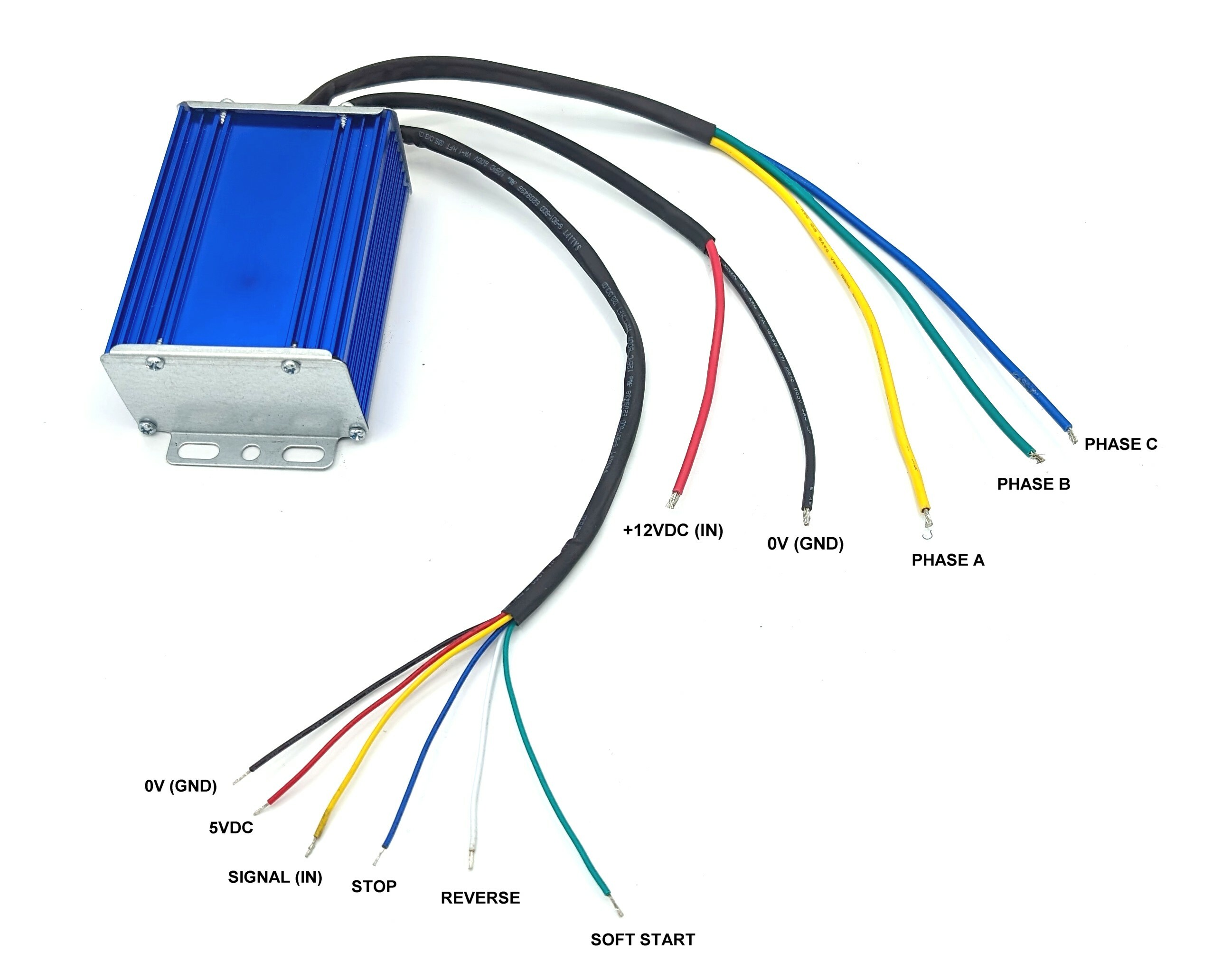
- Connect 3 phase wires (A, B, and C) to the 3 phase wires of your BLDC motor. If you have a sensored BLDC motor, leave the hall sensor wires. This controller does not require hall sensors.
- Connect thick red wire +12VDC (IN) to the positive terminal of your power supply or battery.
- Connect thick black wire 0V (GND) to the negative terminal of your power supply or battery.
- Make sure you connect your controller in the correct polarity. Reverse polarity will damage this controller.
To connect to a pot (potentiometer) for a manual control:

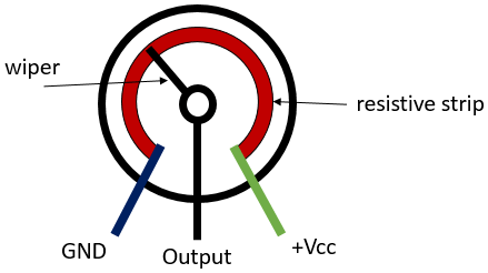
- Connect thin black wire 0V (GND) to your pot's GND.
- Connect thin yellow wire SIGNAL (IN) to your pot's Output.
- Connect thin red wire 5VDC to your pot's +Vcc.
- Introduce an on/off toggle switch between thin black wire and thin white wire REVERSE. This will let you switch between CW and CCW rotations.
- Introduce an on/off toggle switch between thin black wire and thin blue wire STOP. This will let you switch between stop and run functions.
- Introduce an on/off toggle switch between thin black wire and thin green wire SOFT START. This will let you enable/disable the soft-start feature. Soft start's ramp-up time is about 3 seconds.
To connect to a microcontroller:
- Logic voltage has to be 5vdc.
- PWM needs to output at least at frequency of 7 kHz. Maximum frequency is 16 kHz. Connect your PWM signal to the thin yellow wire SIGNAL (IN).
- Switch signals between low (0vdc) and high (5vdc) to the thin white wire REVERSE for CW and CCW rotations.
- Switch signals between low (0vdc) and high (5vdc) to the thin blue wire STOP for stop (low) and run (high) functions.
- Switch signals between low (0vdc) and high (5vdc) to the thin green wire SOFT START for enabling (low) and disabling (high) its feature. Soft start's ramp-up time is about 3 seconds.
To run as a single speed motor:
- Connect thin red wire to thin yellow wire.
- Connect thin green wire to thin black wire to enable the soft-start feature (recommended).
- Introduce an on/off toggle switch between thin black wire and thin white wire REVERSE. This will let you switch between CW and CCW rotations.


